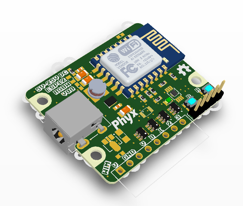
ESP12 RGBW
An ESP12 based RGBW light module
ESP12_RGBW
An ESP12 based RGBW light module using onboard LEDs or capable of controlling external LEDs.
Rev 00
Features
A list of the basic features for the intended use of this board.
- 3V3 level FTDI-compatible UART pin header
- miniature push buttons for reset and boot
- Wide input DC-DC converter (input voltage ranging from 5V to 26V DC)
- 4 FETs capable of sinking 4A
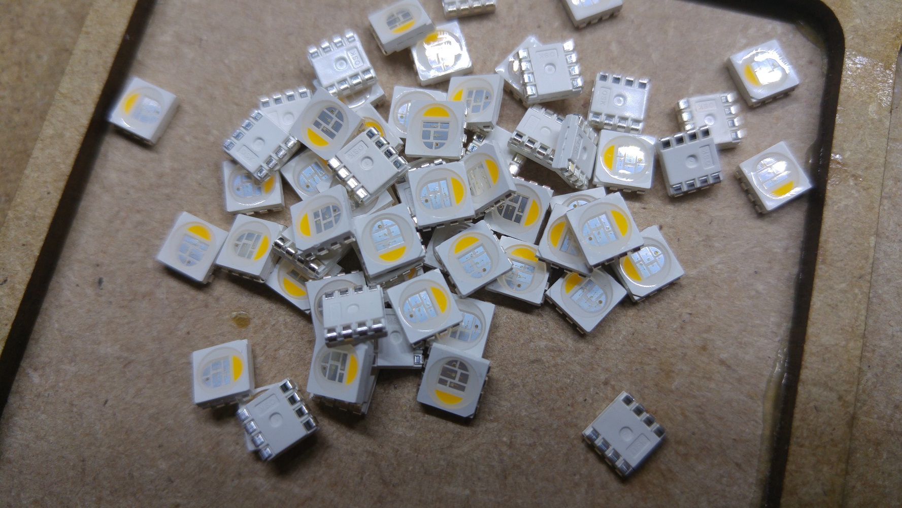
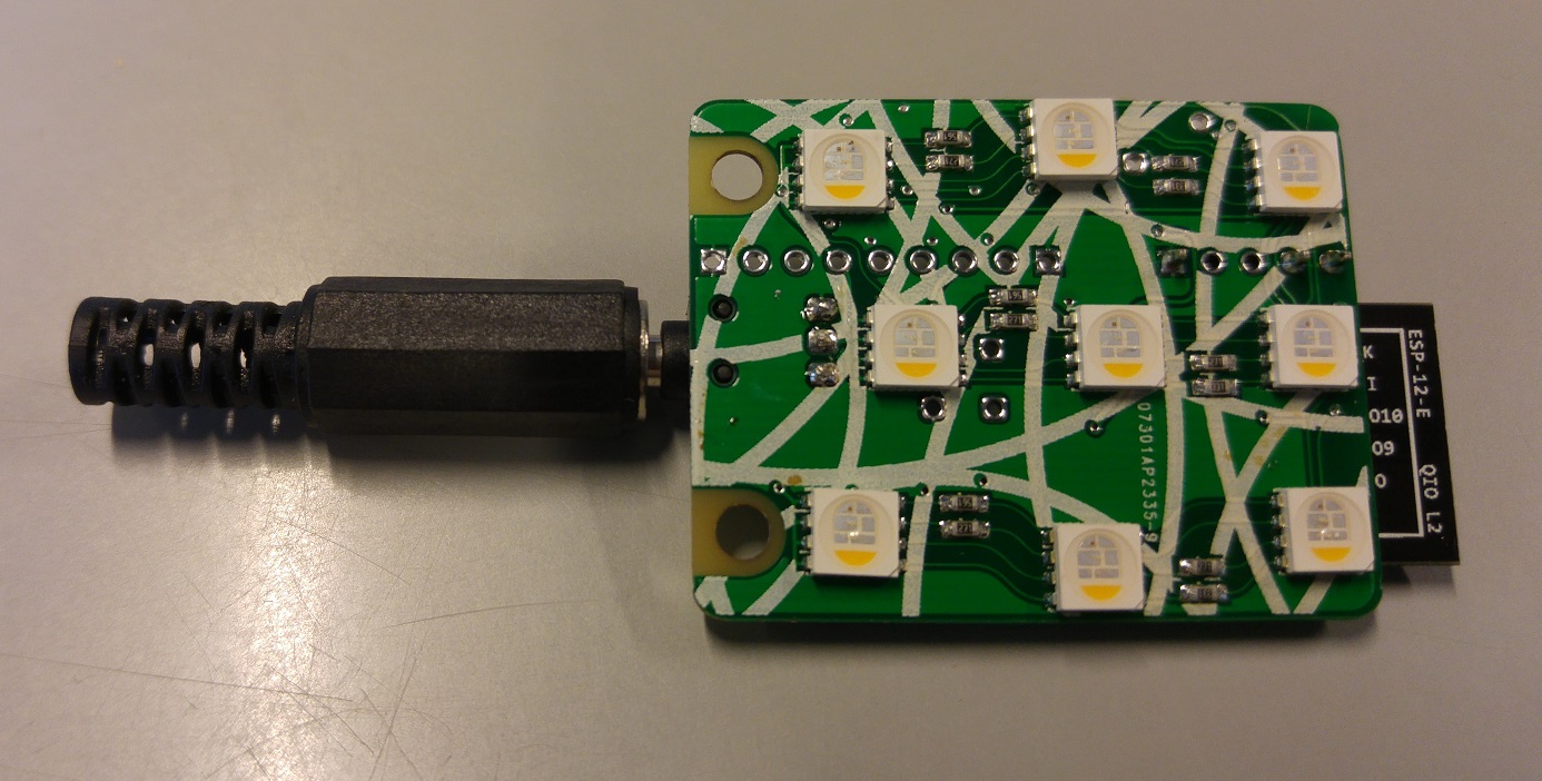
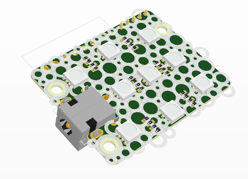
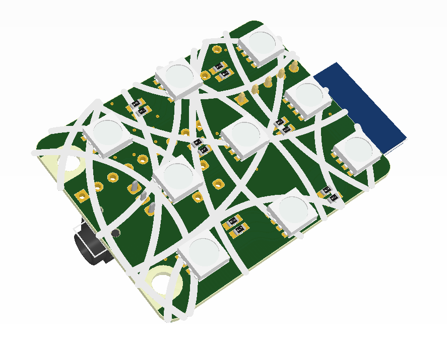
- 3 strings of 3 RGBW LEDs each on the bottom side
Variants
The board has some options, beside the default configuration with the internal LEDs, which allows you to use the same board for different projects. You'll notice an option for a temperature sensor, bi-directional buffer and pluggable terminal block. More info regarding these options are listed below.
Internal LEDs
Default use with either 3, 6 or 9 RGBW LEDs soldered on the bottom side of the PCB. Requires a 12V DC power source. Don't forget to double the resistor values hen using 10mA RGBW LEDs instead of the 20mA LEDs as intended.
External LED strips
If you want to drive external RGB or RGBW LED strip you'll have to solder the pluggable terminal block for and you don't need to solder the DC jack and the internal LEDs. If you do opt for a combination of internal and external LEDs, don't forget to match the working voltage of both. By default the internal LEDs require a working voltage of 12V DC.
Temperature sensor
You can choose either a 1-Wire DS18B20 temperature sensor or a I2C controlled Ti TMP112 temperature sensor. The TMP112 has an higher accuracy.
Bi-directional buffer.
Soldering the dual channel bi-directional buffer TXB0102 makes it possible for the board to control digital LED strips and strings. This buffer requires a 5V reference which can be created by an internal 5V LDO or by supplying the board with 5V and placing a 0R resistor over the input and output pin of the LDO. Using this option you can no longer add the T1 and T2 FETs, hereby loosing 2 PWM or I/O channels.
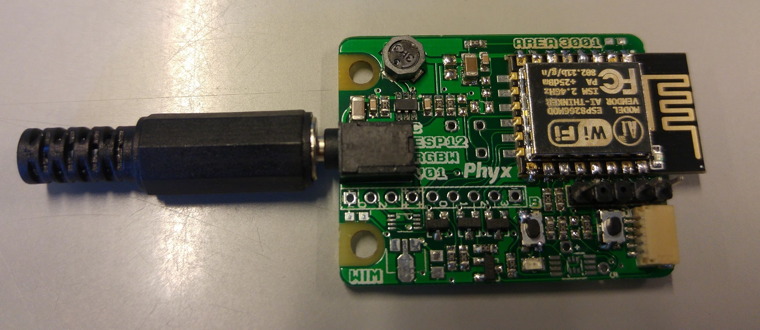
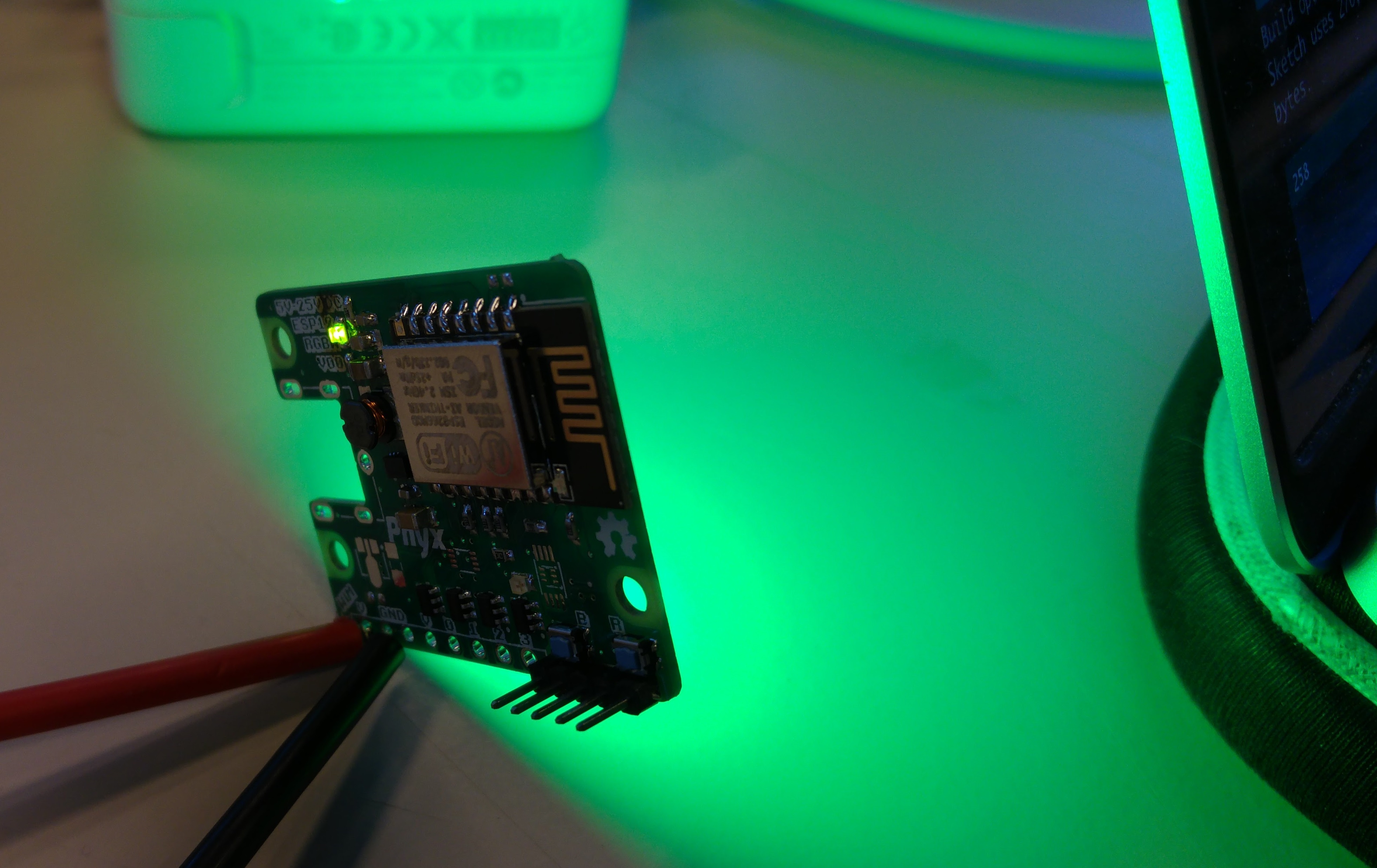
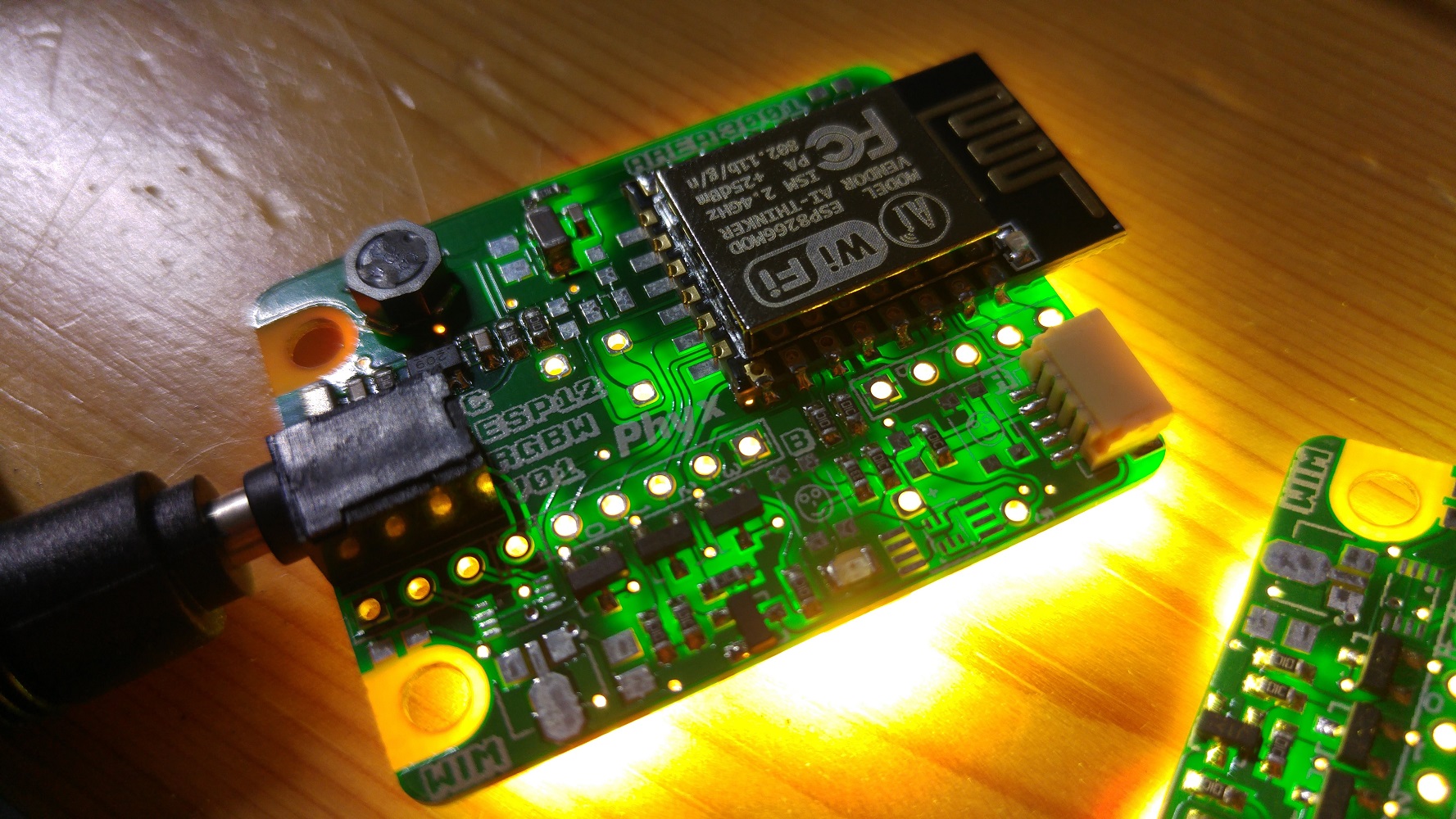
Rev 01
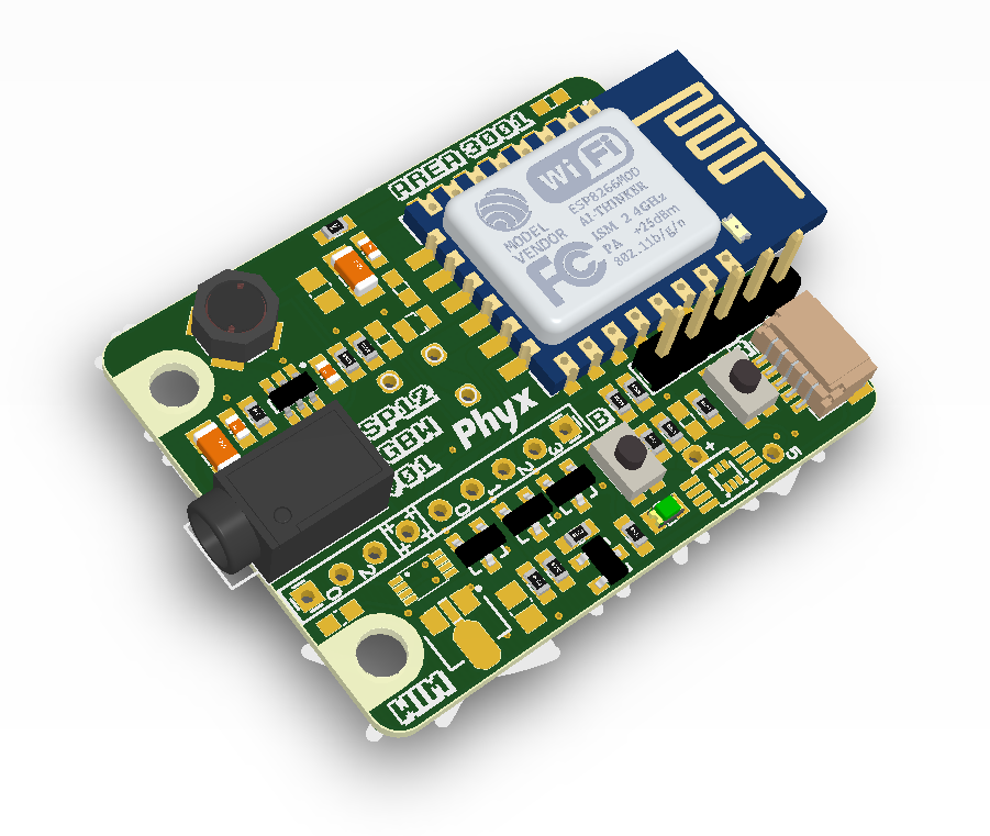
This board is a low cost version of the initial board. The main differences include a cheaper power supply, cheaper DC jack and cheaper FETs. This is done whilst trying to maintain as much veratilaty as the initial version. Although you're no longer able to connect a LED strip directly to this board, you do get access to the PWM signals on a 2.54mm header. The max input voltage is now 15V instead of 26. The option for the 5V level translator and temperature sensor have stayed the same. There is an added option for a panasonic EKMC1601113 PIR motion sensor. The Uart connector now also has the reset and boot signals which allows us to program the boards with a bed of nails. The same signals are available on a 1mm pitch JST header.
Changes
- Cheaper DC-DC power supply based on the Ti TPS562209
- Added EKMC1601113 PIR footprint
- Reduced board size
- Reduced BoM cost
- Smaller DC Jack
Example use
This board was designed to be used with the PWM_RGBW branch of the ESP8266_LIFX project from Area 3001
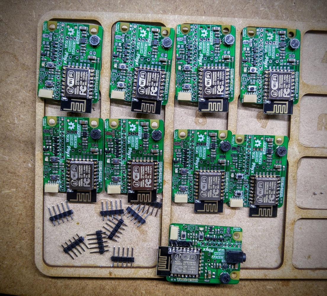
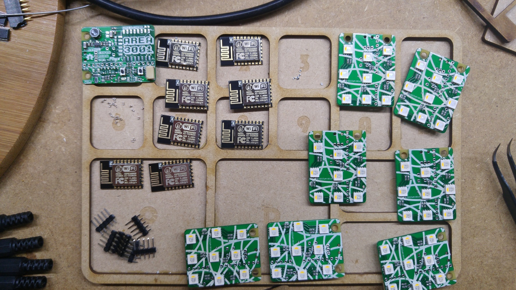
Assembly pictures